


yorks5stringer
-
Posts
7,607 -
Joined
-
Last visited
-
Days Won
1
Content Type
Profiles
Forums
Events
Shop
Articles
Everything posted by yorks5stringer
-
[quote name='Mickeyboro' post='633269' date='Oct 22 2009, 11:06 AM']I don't think it's fair. I just found out Halifax are charging £1 a day for agreed overdrafts, be they 50p or £500. That's a bit unfair too IMO! It's all about squeezing the little people....[/quote] That's to pay for all the gymnasts in suits delivering £5 notes to their customers with the current account. Why don't they use the lift like the rest of us?
-

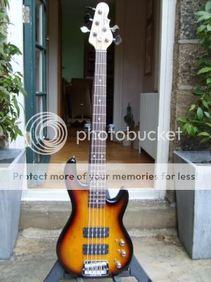
G&L L-2500 Tribute - *** SOLD ***
yorks5stringer replied to Thunderthumbs's topic in Basses For Sale
 I'll do the Bay Trees in their pots ( from the first photo) for £150 each ( sorry for the hi-jack/bump)!
 -
Then I think you had better investigate a weekend return for March/April...! However we're (Idle Hands) playing in Whitley, Doncaster on November the 1st around 5.00 pm if you're interested in popping by?
-
[url="http://cgi.ebay.co.uk/3-4-folding-electric-double-bass-hand-carved-walnut_W0QQitemZ250504669403QQcmdZViewItemQQptZLH_DefaultDomain_0?hash=item3a533de8db"]http://cgi.ebay.co.uk/3-4-folding-electric...=item3a533de8db[/url] Just stumbled across this site, apologies if it has been posted before. They have a number of EDB's, this is the cheapest without a scroll to the headstock. I love the big brass hinge in the middle too! (Maybe this should be moved to the Ebay thread but I thought it could sit in this area)
-
When I saw the thread title I thought someone had eventually twigged I sold Winning Raffle tickets to ringers so I could have all the prizes for myself........ Anyway, it has been mooted for early Spring next year and is dependant on the availability of some special guests....!
-
Our first gig with Amy the new singer and Stagg, my new EDB.
-
I got a very late invitation to this gig, and rolled up without knowing what to expect. What a great line up, all excellent musos, both sets seemed to be over in minutes they were so enjoyable. As you'd expect, my eyes were fixed on Dave Bowie all night ( in a good way!) I think they are in Louth tonight
-
FOR SALE: Thunderbird Bass - £60! Bargain Crazy BOSS GONE MAD!
yorks5stringer replied to Moos3h's topic in Basses For Sale
 I've had an Alfa for 6 years: if you look after them they are fine, it has never let me down. If you look under the bonnet once a year don't buy one, there are plenty of identical euroboxes out there for the masses.... Nice Bass too!
 -
If you use the wet and dry route make sure you have a flat block behind the paper, if you use your finger you could rub a slight groove. I've also used cutting paste (such as T cut) on a foam pad driven by a cordless drill to remove scratches.
-
Without the luxury of a soundperson, I use wireless to listen to us during soundchecks from the back of the room and have never had a problem with interfer...."Lloyd, could you pick up Mrs Smith from Inkerman Street?"
-
band guitarist problem are we being unreaonable
yorks5stringer replied to peety's topic in General Discussion
[quote name='peety' post='625135' date='Oct 13 2009, 04:00 PM']As a band we play quite a diverse range of material from Led Zep to Dolly Parton[/quote] Dolly Parton? She has her knockers but we quite like her. -
The shame is, if Dawsons do resolve this (as they should), we'll never know if it was because they realise they've screwed up big time or because they were threatened with the biggest Bassist forum in Europe.....
-
[quote name='nash' post='622674' date='Oct 10 2009, 08:50 PM']you had the same strings on for a year!?!?!?![/quote] Of course,..... they've only just worn in nicely! Chuffin heck, they cost over a tenner a set now:if it ain't broke.....
-
Tower Of Power at 'Matter' (O2 Arena, London)
yorks5stringer replied to cetera's topic in General Discussion
Yes, it will make up for all the gigs that others "could'nt do" or have been double-booked since Sept...... -
Tower Of Power at 'Matter' (O2 Arena, London)
yorks5stringer replied to cetera's topic in General Discussion
[quote name='BassBunny' post='622138' date='Oct 9 2009, 11:11 PM']BassDay and i'll bring the CD's/DVD's[/quote] Have worked out a cunning plan to do both, it means a swift drive up north after their early saturday gig and a drive across to sunny mancunia on the sunday but I'm worth it! Does your reply imply you are going to see TOP or that you have their CD's and DVD's. If so, I have most of the Cd's but not DVD's.....!! -
Had some strings on my self build/shuker for almost a year then cut my finger, had to gig and leaked blood on them. Wiped it off with a wet wipe thing and then for the next two gigs had soiled fingers. But the strings are OK now, no soiling. Weird.....
-
Tower Of Power at 'Matter' (O2 Arena, London)
yorks5stringer replied to cetera's topic in General Discussion
Bollix, do I go down and see one of my favourite bands in London over the w/e or Bass Day on the Sunday in Manchester....? -
wedding fairs are they a good source of bookings
yorks5stringer replied to peety's topic in General Discussion
Choose your venue and date carefully, we booked at one with a cowboy and it was baking hot inside( and out) and the last day of the premiership (Super Sunday) No-one turned up, we got no bookings and we played for free (cost us £45 fee and all the CD's we produced)....... -
 Having just bought one from another Basschatter I can testify these are great basses. Oh Stephen, make sure you don't mix up the "Pledge" with the "Lynx"
 -
£6 an hour for practice rooms with PA and mics in Leeds, but we generally use a Cricket Club Tea Room for a tenner a night.....but bring our own PA
-
One of the first 'LP's' I bought in the 60's, mono to boot. Trouble with mono was you couldn't really hear the basslines on my old Dansette!
-
The bass cellar - denmark street
yorks5stringer replied to budget bassist's topic in General Discussion
I was driving past PMT in Leeds today so decided to call in, having not visited it since it was Sound Control. Quite a lot of Bass stock including many Sandbergs and some Lodestones, (both the cheap and more expensive ones) as well as the more usual culprits. What struck me was apart from being greeted as I walked in, no-one came up to me when I was looking at all the Sandbergs. Must have been in the shop 20 mins and it wasn't until on my way out when I asked if I could have a free cleaning cloth stacked on a table at the exit that this guy had to go and check if it was OK. I like to think I meet the profile/demographic of someone who could buy anything in the shop by flashing the plastic so was somewhat surprised to be left so alone. This is not a criticism of PMT, just an observation. Mind had to laugh at the 5 String Variax ticketed at £899! -
When we do Weddings and Functions we always make sure we are fed and watered as part of the deal. Best deal we had was at a Restuarant Function where we were offered "anything off the a la carte menu". Yep, Rock n roll.....
-
I always rub snake oil on my Basses ( irony)!
-
[quote name='Jase' post='607653' date='Sep 24 2009, 01:15 PM']I'd love to do a spray job on my P bass.... at the moment it's the most disgusting colour Fender ever issued. Charcoal Frost ....very Midge Ure<_<[/quote] Does that look a little like "burnt vienna"?......
