


-
Posts
428 -
Joined
-
Last visited
Content Type
Profiles
Forums
Events
Shop
Articles
Everything posted by BabyBlueSound
-
I built a Notaklon, there's quite a couple skill levels between these kits and actually soldering a thing 😁
-
 Sigh. Like it's been stated about 9000 times here, it's not about the fakery. It's about the intellectual and actual property theft, the copyright infringement, and the fact that he's doubling down and continues ro make money on Insta, continues to sell the stolen stuff, etc. I guess we can't be upset about blatant disgusting thieves any more without assumptions about what we're assuming? 😁 It's so obvious when someone doesn't even read the topic they respond to.
 -
Post your pedal board - Basschat style!!
BabyBlueSound replied to dudewheresmybass's topic in Effects
Whoah you really cranked up that modulation 😁 I'm super excited you're enjoying the pedal! -
Be aware of ebay and amazon when getting strings. I got fakes from both before. Hope the music shop account is legit!
-
Some cheeky schoolkids fartbombed my door 😁 That's a first. It was not too terrible, I can stink up the place more lol 🦨
-
-
The Short Scale Bass Appreciation Society!
BabyBlueSound replied to Baloney Balderdash's topic in Bass Guitars
Serious personal interest here, but I am still selling a passive Sterling shortie on the Marketplace 😁 -
EB Cobalt user here. Love them, but I had one set that I used for a long time that was getting a bit rusty around the bridge. Did not happen to my next set which I have for like a year now on my Ibanez (yeah, I know)... Not as bright any more of course but still can make the Prec pickup growl quite a bit!
-
For example, promising small gear manufacturers that you'll review their gear, then you don't, then you actually SELL said gear instead of sending back to the manufacturer... I think that's actual theft. Selling the transcript for other people's solos (who are also trying to sell the same transcript they ACTUALLY wrote)... I think that's theft too. Just... read some, man. It was never about the pretending part.
-
Oh, I'm just an idealist, I don't think it will ever happen to anyone who has stolen above a certain threshold 😁 But the above actually happened in US courts, it was a real life example. It just doesn't happen enough, and we're certainly not even going in the right direction.
-
In my opinion accusations aren't enough in this case, I hope someone will take it further, or the victims band together, or something. If you can still sell your stolen gear and continue getting the Instagram money, what's the deterrence for the next up and coming thief? One of these videos (can't even keep up anymore myself) made the point that the penalties need to be BIGGER than the profits, otherwise it's just a low-risk gamble to continue stealing and MAYBE if you get caught, then you get nothing but don't lose anything either. While if you don't get caught, you're a "winner". No. They need to lose, and lose A LOT.
-
If you have seen one of these, you have seen basically all, yes. BUT. The point is, if some guy now wants to look up the sick licks of the faker on YouTube, they will likely stumble upon one of the many exposes, as they should. The guy made sick money via STEALING. Let's not clutch our pearls that some of the wronged YouTubers and actual musicians are now making like £70 on the rageclicks. They deserve more.
-
Good. If the kids can't figure out the obviously fake, this is what is needed to open at least some eyes. I'm happy to give them my views and likes.
-
This one has some more live show examples: https://youtu.be/Jqyt2fk7aNw?si=9nldbl6gB_DFBuHU
-
 Selling a Plüm "Prototype" DIY pedal - Prunes & Custard clone I built. It's a FuzzDog PCB in the enclosure. Prototype, as it's one of the first two I ever made. I usually build 2 identical pedals at the same time at my first attempt, so I have better chances for at least one of them working. This time I got lucky and actually both prototypes work perfectly, and I only need one for myself As it was the start of my learning curve for painting and decorating enclosures, it's got small cosmetic mistakes like chipped corners and getting a bit too close to the drill base, etc, as shown on the photos. Works very nicely with both bass and guitar. For bass, try Drive = 3pm , Mix = 9-10am.
-
- 2
-

-
I am not on Insta, but I don't suppose Mr Tuah apologised yet there, where his main "audience" resides? 😁
-
Post your pedal board - Basschat style!!
BabyBlueSound replied to dudewheresmybass's topic in Effects
What's the top left pedal? And what's the signal chain here? Any of these do the brass from the intro? 😁 -
Post your pedal board - Basschat style!!
BabyBlueSound replied to dudewheresmybass's topic in Effects
You may fire, when ready! -
*£515* Reverend Sentinel Short Scale - Metallic Alpine - *SOLD*
BabyBlueSound replied to sPiKi's topic in Basses For Sale
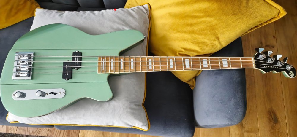 This keeps coming up and I have to keep remindig myself, I'm here to SELL a bass, not to buy a new one... 😅
 -
Finally! I mean all she had to do is record over 9000 songs perfectly, through multiple decades! 😁 Like one does.
-
My 5yo has a cheapo uke she gets out every now and then, and I also share my u-bass with her. At this age she doesn't really care about fretting, but the right hand rhythm is already starting to show as she's trying to mimic the music. I guess it builds a foundation!
-
Look I am pretty far away from being a luthier, but sounds like those frets might need a bit of grinding, they're possibly fractions of millimeters higher than they should be. I had buzzy frets around the 16th-17th where you can't really set the neck, AND I had high action. A luthier grinding them a bit fixed them completely.
-
Scribd.com has a free trial, where you can legally download Brian's (and of course other) books in PDF. I am about to read it on the train.
-
Struggling with sound engineering guitarist
BabyBlueSound replied to mrtcat's topic in General Discussion
Just the average egoguitarist approach to mixing. Nothing new under the sun 😁 OF COURSE everyone wants to hear his crunchy tones and nothing else, that's why they're there for on the wedding! -
Post your pedal board - Basschat style!!
BabyBlueSound replied to dudewheresmybass's topic in Effects
Of course I have to ask, what does the one-knob red star do? -
I know HOW to do it, I just don't know how to do it PROPERLY! 😁 There must be a way, someone must have learned a lesson, etc... does it even make sense on a wider neck?


