


rwillett
-
Posts
2,134 -
Joined
-
Last visited
-
Days Won
7
Content Type
Profiles
Forums
Events
Shop
Articles
Everything posted by rwillett
-
@Rosie C Thanks for this, I had a feeling it was just my latest dumb question in a long trail of them. Pleased its not only me
-
The weather here has slightly dropped off, however we have had reports of a bearded bloke collecting pairs of animals, and an awful lot of wood has gone missing. There seems to be some sort of structure being put up on the top of Ingleborough as well, no ones quite sure what's going on, but seems a dumb place to build a boat to me.... Anyway, I might get chance to do a bit more on the cab today after a week in London. I was thinking about a speaker grill and making sure I put some mounting points on, I rather like the metal grills that you can get on eBay. Is there a minium offset from the speaker that a metal grill must be, I look at the metal grill compared to speaker cloth and wonder does it either resonate or attenuate the sound. Clearly people use metal grills and they look great, but wondered if they need to be 10mm (or another minimum distance) from the speaker or the holes need to be a certain size, do you need rubber mounts on them to stop them vibrating? I can still put T-Nuts in if necessary for mounting points, even though the front and rear panels are now glued in, but I'd rather plan for it now than having to take it all apart again. Thoughts welcomed. Thanks Rob
-
How was Your rehearsal last morning or night ?
rwillett replied to nilorius's topic in General Discussion
Given the weather up here, we might come along so long as it's indoors... -
Brilliant, Now I know who to ask...
-
Like it when things like that happen. I used to have a 73 Alfa Romeo 2L GTV. This is the old Giulia shape. Nice car, 90-100mph top speed. I was driving out of Brighton up the long hill toward the M23 and I saw two very large headlamps behind me. I thought it was a Land-rover. Put my foot down and they kept getting closer. Turns out it was a 2CV overtaking me at probably close to 90mph uphill. The two men waved and laughed as they went by me. I couldn't keep up. Q-cars are brilliant. I have no idea what the 2CV had under the bonnet but it certainly wasn't stock. There is a hill climbing 2CV with a BMW engine in but this was 30 years ago so it's not that one. I was humbled by the 2CV and I did try to catch them up but they were long gone. Rob
-
Now that's a purrty guitar....
-
Phil Thanks for this. I did read an article that said AWG 4 (yep that's not a typo) should be used. Not sure I've seen anything that thick TBH. My AWG 16 will be fine then. I'll cut a bit off and solder it down. Does the cable need to be glued down to stop vibration at all? I'm assuming not but checking anyway. Thanks Rob
-
I think you are confusing me with somebody who has an inkling about what he is doing. Honoured that I am mentioned in the same sentence as real luthiers and semi-pro hobbyists, but these people know what they are talking about whereas I am merely one page away from disaster on each build. I am in awe of some of the builds on this site. No sarcasm, no irony, no snide comments from me, there are fabulous designers and builders here and I would love to have 1% of their talent. Thanks Rob
- 31 replies
-
- 2
-

-
- ac guitars
- acg
- (and 6 more)
-
Misson control has allowed me to put the speaker on the dining room table to glue the front and rear panels in. It is basically freezing up here. Doing the rear panel first. The front panel is on the right hand side of the picture. Next jobs: Glue front panel in tonight. Route the edges so there's a nice curve Solder speaker wire to the speaker <-- What size wire is OK for 250W? I definitely have AWG16 and might have some thicker in a box somewhere in my basement. I've heard AWG 14 should be used Fill and sand any problems. Paint front baffle matt black. Take off side handles and rear speakon panel, and paint the wood matt black. I'll mask this area off before the Armacab goes on. Assemble, check all OK Check it all works. Wait for warm weather to do the Armacab. - July 2027?
-
Guess who has spent the week measuring, drilling, fitting and screwing in 34 M3 and M4 t-nuts? Now you tell me Rob
-
10C? That's a barmy sunny day in North Yorkshire. It's currently hovering between 0C and 5C during the day. Little chance of getting to 10C outside for a few weeks I know you lot down in Somerset have a Caribbean climate all year round, but we don't. The reason we put ferrets down our trousers is to keep warm I'll put the holes and t-nuts in, glue the front and rear panels in, round the edges and wait for it to warm up before applying the Armacab. I suppose it'll give me time to get the other speaker cab done. Thanks Rob
-
I think I'll drill the holes, fit the t-nuts, put some sacrificial M3 bolts through, and then cover it. I want to get the speaker working as I have another to assemble and want them done for Xmas.If the covering has to wait, I'll accept that. Rob
-
Did you get issued a mandatory flat cap and t'ferret? We will get back on track though Rob
-
Seems perfectly acceptable to me... I live in a small village in the Dales, sometimes it feels like the village that time forgot. In fact you can see my village here in this YouTube video from 1962. Apart from the cars, it looks exactly the same. I live just before the house that you can see the side off on the right., One of our gateposts can be seen, but not the house. Just about everything else is identical, though the trees are 60 years older and taller.
-
When I was 7-8, my best friends dad used to make steam engines, He'd do everything including making the tiny nuts and bolts. It could take him 10-12 years in his little shed and little lathe. His last project was a flat four engine based on the original engine that was supposed to go in the Morris Minor. The engine that did go in was a more normal straight and upright four. This is why the engine bay in an old Morris Minor is so wide and why you could drop a somewhat large engine in to play with, you needed to upgrade the mounts but a small V8 has been made to fit. This useless fact was brought to you by Car Nerds 2025 Rob
-
Definitely an option, not sure how the Armacab would work here, is it so thick that it would stay in place, or would it ooze? Its very cold here and very wet so can't really test anything. T'other half has made it very clear, no painting or cab work in the house under any circumstances Rob
-
I'm getting to the stage when I'm going to coat the cab in Armacab. However I want to make sure I understand some options here. I'm going to add in two mounting blocks for the Warwick Gnome amp on the back of the cab and on the top of the cab, so the Gnome can be positioned on the back or on the top. It's just to add some flexibility This is the drill guide, a quick hack TBH. I would drill 4mm holes here and then use an M3 pronged T-nut on the inside of the cab to allow the countersunk screws to bolt into the T-Nut. Not a fan of simple screws here. Now I'm trying to work out the order of doing this work. Where I have done this before, which is for the Fane speaker, the front port and back panel, I would drill the right size hole, put the t-nut at the back into the hole, so an M3 T-Nut requires an M4 hole. I would then drill an M4 hole in a scrap piece of wood, put a long M3 bolt through the scrap wood with a heavy duty washer and then through the hole in the cab into the T-Nut. I would then tighten the M3 bolt up, it would tighten against the scrap wood and slowly pull the T-Nut into the inside of the cabinet, the scrap wood would protect the outside of the cabinet as I put quite a lot of force on it. If I do all of this before I paint with Armacab, then I will need to protect the holes I've drilled so Armacab doesn't go in them. I can easily put some sacrificial bolts through the holes to protect them, However never used Armcab before so not sure, if the Armacab would splinter if I then took the sacrificial bolts out, when the armacab is dried. OR should I paint the cabinet with Armcab for a few coats and then drill the holes afterwards. Would putting the scrapwood on damage the surface of the Armacab. Could I even drill through the Armacab, not sure how tough it is. I can test it but it might a few days to dry so am now into "Paralysis by Analysis" as I work through what my options are. Any thoughts welcomed. Rob
-
That's very true. I used to drive up the A1 regularly and would always stop near the Nene Valley railway as it was a pit half way from London to York. Never had the opportunity to go on it. I do become a little boy when near a steam engine. No idea why as they had long gone when I was younger.
-
Hi @Si600 And I know which is far more usable. I could probably cobble together a better bass from the firewood than the bass for sale. I'm going to watch it just to see if any fool is parted from his money. Also as there is a discount on three bags or more I could probably get half a bag or so extra.
-
Possibly overpriced by 100x https://ebay.us/m/ffFDAS
-
Or get someone to print a port with a flange, a gasket and three mounting holes so that it covers the hole neatly. Just a thought. Rob
-
I brought a red Telecaster kit two years ago. I paid a £160 or so. Didn't know any better. Had fun building it but the neck was junk, took it to a decent guitar shop to get it set up and they spent quite a lot of time trying to fix it and said it was impossible to get it right across all the neck. So if one end of the the neck was right, the other end wasnt. They refused to take any payment for their time as it was throwing good money after bad. I gave it to a local school and told them it was poor quality, I think they use it in school plays as a prop. I won't put the name here but I'd advise the OP to DM me. Rob
-
Ah! Didn't realise that. That makes sense now. I was going to put a grill on as well. So matt black(or red Hammerite) is fine on the baffle.
-
Thanks. Did you mask off the area where the speaker meets the front baffle? I would have thought that should be done, to ensure a tight fit, but happy to be advised otherwise. Rob
-
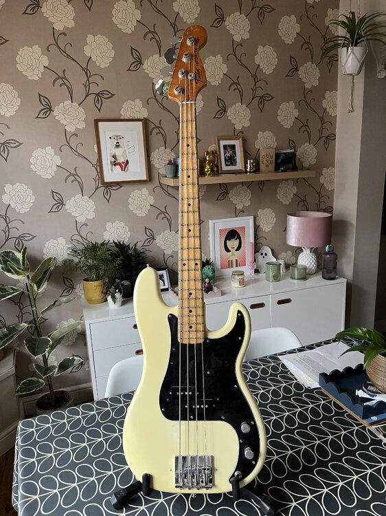 Mmmm.... Now that is a work of beauty. Lovely amounts of usage. No showroom queen (in a really good way), you'd have no issues using this. Thankfully I'm completely skint but that's a great looking bass.


