


rwillett
-
Posts
2,049 -
Joined
-
Last visited
-
Days Won
7
Content Type
Profiles
Forums
Events
Shop
Articles
Everything posted by rwillett
-
He has cut down...
-
I'm trying to work out if this is actually an issue or not. I know nothing about Rickenbackers apart from Macca and Lemmy played them. I keep hearing that the bridge is difficult but surely after all these years they must have fixed this problem? Or is it just a running joke that nobody does adjust them? Thanks Rob
-
Have they a cheap 62 Jazz as well?
-
@neepheid We'll take everything I can find in the house. We'll make it work one way or another. Rob
-
Ron All help welcomed but it's chairs and tables so it's not a.massive amount of work. However it would be good to see you and you then get the advantage of an empty (ish) hall to play in 😊 I have asked if the lady I jam with will come and bring her mobile drum kit. Her main drum kit appears to be larger than John Bonhams set from LZ 😊
-
Food now sorted. I've arranged for a special tea delivery for @ossyrocks from Farrers Tea & Coffee merchants in Kendal, they're sending a local van just for me, and a local dairy farm has helped chip in with milk. The village hall will be open from around 08:00 for people to get in. Will anybody apart from myself (and possibly @neepheid) be coming at that time? The intention is to finish around 16:00 (ish) as I have to be in York later than evening. Rob
-
Will Basschat survive the Online Safety Act?
rwillett replied to fretmeister's topic in General Discussion
You are correct that most will be, I hadn't considered that, but how are Ofcom going to know? If they develop a Web crawler, does it respect the robots.txt file? This is going to be very difficult for them to police. -
Will Basschat survive the Online Safety Act?
rwillett replied to fretmeister's topic in General Discussion
I think this is the key line here "Websites will have to change the algorithms that recommend content to young people and introduce beefed-up age checks or face big fines, the UK media regulator has confirmed." My emphasis added. This is targetting the social media apps that push things to you. Basschat doesn't recommend things, also we don't have any young people. I will get around to reading the legislation and the Ofcom stuff once the bass bash is over and I have a free few hours. Just for information, there are circa 11.1M .co.uk domains registered, not all of which are live. A simple thought experiment on how much work is needed to process this information if its only 10 mins per website per year manually. You can't do everything by computer yet. UK law isn't very happy with fully automated decision making by UK Govt depts. Assume 50% are live so that's 5M websites = 5,000,000 * 10 = 50M minutes So 50M minutes = 833,333 hours. 833,333 hours = 120,000 days (ish) Assuming lunch breaks 120,000 days = circa 550 people As of 31/3/23 Ofcom had circa 1,300 employees. So even a cursory 10 min check will require a 41% increase in employees. I know that the civil service is doing it's best to cap new recruitment. Ofcom is considered a quango and whilst it is not subject to civil service recruitment blocks, its funded by frees from industry as well as grants from central govt. It will not be capable of recruiting 550 people or 275 people or even 140 people for a 2.5 min check. Somebody has to answer the phones, report on how many websites are checked, this is all manual. There are no robots here. I'm also not aware of any software development that might be taking place to do this work. That doesn't mean it hasn't happened as I'm focussed around certain areas of UK Govt, but I might have heard. As I've said before, the focus here will be on the large social media companies. Basschat is in the low level noise here (pun intended) Rob -
We're down to our last few days, so I think we have 15 bass players plus one very significant other who may or may not join us for lunch (though she is very welcome) and may or may not bring mutt (that's the dog, not @bigthumb) @rwillett @bigthumb+ 1 <-- Vegetarian @neepheid @ead @80Hz @GreeneKing <-- Vegetarian @stevie @nekomatic @ossyrocks <-- Endless tea @peterjam <-- Eats anything, likes small children. @doomkeeper @Frank Blank @zbd1960 @bagsieblue <-- Vegetarian @Mottlefeeder <-- Vegetarian I count five vegetarians so that leaves 10-11 non vegetarians. Thankfully we have less than twenty otherwise I run out of toes. I'll ensure we have a collection of circa. 30% vegetarian pizzas and the rest a range of fairly mild pizzas up to quite spicy ones. As I have no sense of smell, though I can taste but its reduced, I tend to go for the spicier one. I do not judge people here I'll also get some salads, 300 tea bags for @ossyrocks, 4 gallons of milk for @ossyrocks (do you want sugar as well?). We'll have the village hall from when I drag myself out of bed, say 07:30 to around 16:45 or so on Saturday afternoon. We can park on the road outside the village hall. Can I ask that people unload and then move their cars please onto the main road please and not park behind the village hall as it is in use for other things and I have to live with the neighbours for another year. There is power in the hall but you might want extension leads. We have loads of tables and chairs. Any questions please ask. Rob
-
That's nice of your Missus. Is she going to stay with you or wants to do something for herself? Clapham is a vast metropolis full of wonder and variety, nah, thats not it at all. If she likes walking, then it's great. We have fabulous walks literally on our door step. Also mountain biking is big here and you can easily spend eight hours just taking the trails within a few miles of us. If she likes studying sheep, then we are the centre of the UK for sheep. We have so many sheep, she'll fall asleep counting them. That just about exhausts Claphams attractions. Settle is 15 mins down the road and is lovely but small, Kirkby Lonsdale is 15 mins back up the A65 and is quite delightful but not much bigger. Clapham village hall has free GB wifi with B4RN so she can stay connected. If she wanst to do something specific, PM me and I'll help advise. Dogs are exceptionally welcome here, all the pubs welcome them otherwise they would have no business, a fair few restaurants, shops and cafes do as well. My dog will pop into the village hall at various times during the day. The village hall has a vast quantity of chairs and tables, I suggest we put you in the middle so we can rally to your calls of "Boy, that bass over there to me and quick now" as fast as we can. Sadly as it's GCSE and A level time, both my daughters are revising so they can't wait on you hand and foot. I'd suggest you bring your own cushions. Will she want food, zero issues if she does? Rob
-
Accidental NBD... G&L Tribute SB-2 - the return
rwillett replied to neepheid's topic in Bass Guitars
I can just see Matt sitting on top of the car with strings through the window to the steering wheel and the car loaded with gear. -
Where is this source?
-
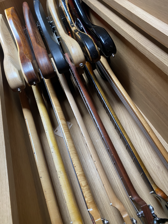
I have a few you can use if by some quirk of space-time physics you can't put 479 guitars in a Mitsubishi colt.
-
I thoughly enjoyed the set. Songs were great, really tight band.
-
The sound is excellent
-
The Out and Out Blues Band with our very own @ossyrocks on bass
-
Oh yes 😊
-
Let me know what you need. Do you have a model to work from? Printing is the easy bit...
-
And if every splinter that came from the cross was collected, it would be bigger than the Amazon rain forest. Strange how some religions venerate this sort of thing. Mind you I have circa 1.5M old cigarette and trade cards my dad and I collected over 25 years, so I'm the last person who can criticise this sort of thing. In my defence, I do not think they have magical or mystical powers though...
-
What does that monster weigh? Is it on wheels and motorised?
-
 Where do we buy tickets and popcorn?
 -
Oh god, I wish I hadn't seen this thread....
-
Accidental NBD... G&L Tribute SB-2 - the return
rwillett replied to neepheid's topic in Bass Guitars
Well bring something interesting to the Bass Bash in a few weeks.... -
Try the low fibre cables, they're far easier on the teeth...


