


AngelLaHash
-
Posts
145 -
Joined
-
Last visited
Content Type
Profiles
Forums
Events
Shop
Articles
Posts posted by AngelLaHash
-
-
what type of SWITCH do you have for the PICK UP.. 2P2T (on/on/on)
well you would need another Pole to be able to change that so the battery is turn off and state
3P4T maybe a rotary as i dont know of a toggle

well that one looks like its powering up the PreAmp .. should really go to a Switch first to turn it off...other wise there is Power to the PCB
Same with this one but the Negitive side of the battery is going to the Jack plug ground.. tho the grounds dont seem to go to ground but that might compleat the circuit tho
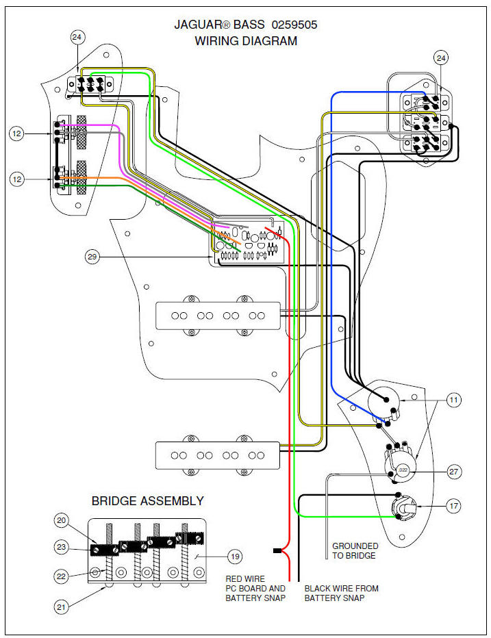
I do think its just a short tho -
OH NAFF OFF.. i didnt take the Measurment from there.. .i cut the hole just by EYE level about 3 Year ago
So STOP ya Jibbing young WHIPPER SNAPPER
AND I DID POST ages ago that you cant take the MEASURMENTS from there.. BUT YOU COULDNT READ IT -
Right i was trying to EXPLAIN that.. i do understand that I cant use the PICK GUARD as a JUDGEMENT to were the PICKUP should go because of the were the NECK really ends on the BODY.... That is why i KNOW i put it in the WRONG place first off.
This is WHY i POSTED the PICTURE to show this
If you look at the LINK you will see i was in the chat from 2yr ago
(im going to have to stop for a while as its driving me Nuts some posts) -
but you cant use a Pick Guard as judgement from the Neck
-
I hear the MM's are a bit shorter

I did cut in to the body before i found that Forum Page, but if i make my own Pick Guard i can Hit the HOLE!
I dont think it would be good to have one Pickup under another like it would be with a PMM
So would having it in Place were the Jazz Bridge Pick be better and change it so i can select MM/Top/Bottom Pickups
[url="http://www.talkbass.com/forum/f8/pickup-spacing-comparison-652372/"]http://www.talkbass....parison-652372/[/url] -
for it to be using batteries so much means its making a connection..
I was suggesting a MOD to make sure the Battery wasnt used up..as i said i dont know what design this is .. a LOT of makers of ITEMS make FAULTS built in..
IE fixing Laptops .. noticed a lot of faults with were the PSU plugs in.. because a few laptops dont have any thing bit a 2mm bit of plastic holding back the connection box and nothing behind it.. That is waiting for it to happen -
Yep that's the company, i dont mind getting them from china or any were.. just couldnt find them else were.. dont even mind bulk.. as longs as they are better value for money than the UK
-
[quote name='Immo' timestamp='1392030973' post='2363714']
Buy some raw pickguard material and create a pickguard of whatever shape you like
[/quote]
Yes thats what i got at the moment.. i guess getting time to cut it out.. Maybe Leave a lot of play for errors. -
Isnt there some Mod you could do so that it Turns OFF fully.. I could hook some thing up via a Volume Pot i guess
Hook Ground to the Jack ..
If you have a Pickup Selection switch wouldnt take much to replace and put in a off positions maybe
Tried to google for the circuit but found so many types and not active ones !! -
I think ahpook is correct it is a Ground, but to find out where it lives on the PCB board's
I would guess that it would be a Black wire that goes to the Switch Board.
Pickup Cable (Gray) and Ground (Black) coming from the Pickups Area.. then all go to the Switch,
Look at the soilder joins and see if some thing is attach, if some thing is missing then that MIGHT be it but keep looking, with hope only one thing would be missing. -
I am doing a PMM one but it dosnt look Pritty

I hope i got the MM in the correct place but i would like some thing to Cover the MESS i made with Chopping out the hole :'( -
May i ask were you brought this 4P2T (On/On/On) from, i use them for Flip Coils on a Strat design, but cost £5 a pop
-
I'll do my best to be there, be good for me to talk to humans than Forums..10th May a Long way off .. on the Good POINT.. DODGEBALL club near By

-
I'm not sure what to say about this,
Like how they are working for themself,
Not sure were the pickups are tho, ie there is no space for them.
Guessing its going to be a Bridge than a Tremelo, and the jack is on the scratch plate (wood is a nice touch)
Think they could make money and put the profits back in for tools and cheaper musical instruments for the community
But its Africa, (trust with the money) you could get some nice custom designs for a good price out tho, with a wooden scratch plate
Its a Catch 22, and the only way out, is to have a base in the EU selling the guitars for them, or making them custom. -
My current set up for my P-Bass is 2xHex Switching giving me a Range of 200pF to 100nF in 200pF steps
thats just the tone contol's it also has [url="http://www.impossibleband.com/projets-electroniques/megatone/megatone---archive#TOC-Megatone-36"]http://www.impossibleband.com/projets-electroniques/megatone/megatone---archive#TOC-Megatone-36[/url]
sort of like that but, i have more a range on the Caps and the "Boost" Resister has more 4 ranges 15k, 150K and 1K5 and direct to ground.
So i just need to play around with them to find my area of perfection -
Well Ive got a Induction Meter.. i would like to learn how you figure out what would be Best than what Suits and is ABOUT ok for the pickup
Man trys for Perfection, and sadly falls a lot of the time -
First off, thanks you for explainging the bigger picture to me Dincz

So what about the Bleed cap that is put in,
People use 1nF, 1nF with a Resister (220K-120K) and 200pF
That chances the Freq and the Impedance Xc=1/(2*Pi*C*f)
Would it be best to have some Calculation to balance between the Pickups and the Volume pot -
I found removing easy enough and cleaning the "groove"
the replacing it and sticking in a new one was a bit more harder for me, but i'll learn there are some good Videos on YouTube i think
and books,
[b] [font=opendyslexic]Guitar Player: Repair Guide[/font][/b]
[url="http://www.amazon.co.uk/gp/product/0879309210/ref=oh_details_o01_s00_i00?ie=UTF8&psc=1"]http://www.amazon.co.uk/gp/product/0879309210/ref=oh_details_o01_s00_i00?ie=UTF8&psc=1[/url]
might want to loan it out from the Libary or some thing -
I'm not sure where to start, so I'll just type what i am thinking to a degree.
The Volume pot is being used as a [size=3][font=opendyslexic]potential [/font][/size]Divider,
Input one side, middle the Output and other side is GROUND.
So that what Voltage is made from the Pickups, from the strings pulling the Magnets via a Copper coil.
As far as I know that the voltage out of these things is dam small
And its not AC to speak of but a frequence range, normally 0-6KHz i think i read some were, but human hearing is 0-20KHz
These are just things I've read Online (so not 100% the Truth)
Is divided between the Two half's of the POT.
So why 250K, why not 50K or like I'm told a good value for Humbuckle Picks up's is 500K.
I know Electronics and Electrical's but i dont normally use a Pickup as a Power Supplie or do circuits with a "AC" circuits. -
Get a Pot (Dual or Single)
Take it apart
Paint over the OUTER Track with Conductive Paint
Cut the Track in the middle with a thin hair line crack (making sure each side isnt connection any more)
and put it all back to gether,
Making a 1P2T Switch,
Left and Right lugs one say the outputs and the Common the middle lug is the Common.
Would this stop you POPING sound that you get from a, Spring loaded switch (may not have a SPRING so to speak but a way of flipping from one connector to another)
And if you want a 2P2T you would need to have a Dual Pot and do the same to each plate. -
I think RS do pickup but not sure of all the places there based (Nottingham)
Maplin is the Parts Store a bit dear but ok
Or just ask on the site if any one can sell you a part for cheap.
I did have some of these, i was using them for a project 10yr ago i think on a bread board -
If you go to talk bass.com there is a'guy who could send you all the circuits and in English
Name of cadfaed, nice guy and willing to help -
Volume: output:input:ground (its up to you to get it the right way for your numbers but both ways work)
Tone: cap(ground) :input (don't care were you put them as long as they are next to each other, so one HAS to be in the middle) -
I used to use a kind of rubber like you find in them pens you can rub out
Dark black/gray, but most rubbers should get the green off
What we use in circuits when designing them
But isn't it like eating the copper, I kniw I got a old circuit and its lime green and no track.
PJing my P
in Repairs and Technical
Posted
Sorry Ou7Shined.. i was reading it in the wrong tone.. been ask to stop..
i didnt know NAFF was such a Upsetting word.. i was getting more p .. and to bring it down i used soft words like Naff as used by Princess Margret
But been told Cant Do that.. so i'll have to go
Power to the People